Intro
 Traffic light simulation is a classic text book problem used to demonstrate a finite state machine. A FSM is a system with finite states, finite inputs, finite outputs. It has a known number of states, inputs, and outputs. You can join team Mealy or team Moore, sometimes it matter, either way everybody wins, and you can switch teams in most cases. The state machine implementation in this project is an example of a Moore machine. Output depends on the current state and the next state depends on current state and input.
output = output(current_state)
next_state = state_transition(current_state,input)
Opposed to Mealy model where output depends on current state and input and next state depends on current state and input.
output = output(current_state,input)
This traffic light simulation will simulate two one-way streets. One street has priority (north to south) and will stay green unless there’s a reason to switch.
Components
Hardware
- PIC16f1829
- Any micriocontroller will do.
- 6x LED’s
- 2x Red 2x Yellow 2x Green to simulate traffic lights.
- 6x 330 ohm resistors
- Current limiting resistors for LED’s.
- 4.7k ohm resistors
- Pull down resistors for switches.
- 2x Push button switches
- Simulate traffic sensor.
- Breadboard
- Jumper Wires
- Popsicle sticks
- Bottle caps
- Card board
Software
- MPLABX
- MCC Microchip Code Configurator
- EasyEDA
Schematic
Design
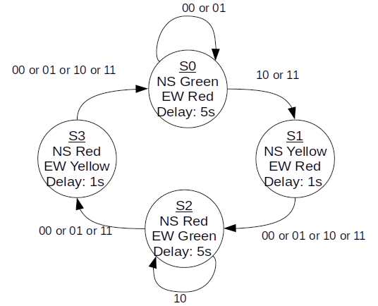
I think its easier to start from a state diagram, meale or moore. Then build the state table, then code.

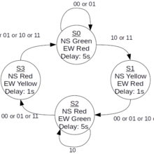
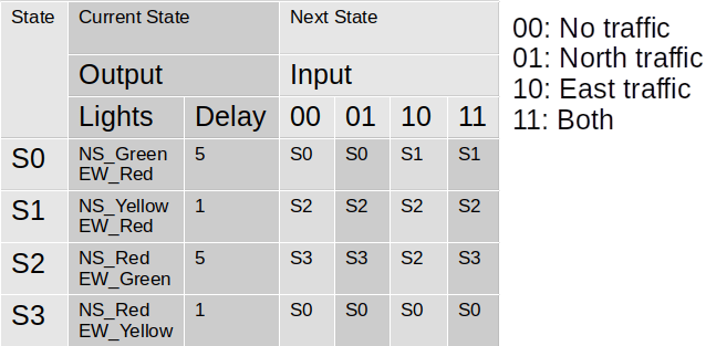
With the state graph done, its easy to build the state table. Looking at state0 (S0) if there’s no input (no traffic) then the next state is S0 (main light stays green). If there’s east bound traffic (0b10) then the next state will be S1 (north to south light changes to yellow). the Full transition will be S0 -> S1 -> S2 -> S2 and stay in S2 until there’s no east bound traffic or if north bound traffic arrives.

Software
Its common to see a state machine implemented as “if” or “switch” case statement. Another approach is to use a struct. using a stuct condenses the state machine logic quite a lot and makes debugging or adjusting states easy.
The state table created earlier can nearly be copy pasted to the state table for the program.
const struct state traffic_controller[4] = {
    //output,           delay,  next state
    //                           00  01  10  11
    {NS_GREEN|EW_RED,   5,      {S0, S0, S1, S1}},  // S0
    {NS_YELLOW|EW_RED,  1,      {S2, S2, S2, S2}},  // S1
    {NS_RED|EW_GREEN,   5,      {S3, S3, S2, S3}},  // S2
    {NS_RED|EW_YELLOW,  1,      {S0, S0, S0, S0}}   // S3
};
The state machine can be run in the main while loop with four lines
- Set output
- Wait delay
- Read input
- Set next state
while (1)
{
    //set output. LED's connected to port C
    LATC = traffic_controller[state].output;
    //wait state
    delay_s(traffic_controller[state].delay);
    //read buttons
    input = (uint8_t)(IO_RB5_PORT|(IO_RB6_PORT<<1u));
    //set next state
    state = traffic_controller[state].next[input];
}
Hardware
Card board, popsicle sticks, and hot glue.

Source files
Resource
Introduction to ARM Cortex-M Microcontrollers (Jonathan W. Valvano)
