Intro
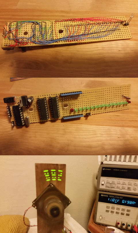
 These things are fun to put together and interesting how a single line of LEDs moving fast enough, can trick our eyes into seeing more. This is the effect of Persistence Of Vision.
- Displaying RPM
- Displaying rpm,flower/star, time format
Components
Hardware
- 9v battery
- LM7805 regulator
- Provide a regulated 5v supply from 9v source for the components on the proto board. The LM78xx series indicates its 5v regulator by the 05 in its name, and has a ~2v drop out meaning, at least 7v source will be needed to get a regulated 5v output.
- 47uF capacitor
- Bypass capacitor for 7805 regulator. For projects with low load demands a bypass capacitor probably isn’t necessary, but add them anyway.
- Switch
- Simple switch to turn on/off this project.
- PIC16F84A
- 18 pin dip, 1.75kb flash, one 8-bit timer, 20MHz max oscillator. This micro is small in size for a DIP package and minimal in features, but it has everything that’s needed for this project. The available program space could be an issue if functionality is expanded in a later project.
- 20 MHz crystal oscillator
- 20Mhz crystal for pic micro.
- 2x 74LS373 Octal Latch
- 3-state octal latch for controlling 8 LEDs each. 74LS devices are better suited to sinking current and this is seen in the data sheet, IOH (logic high) = -2.6ma max, IOL (logic low) = 24ma max. 74LS373 could source current higher than 2.6ma, however the safety of the device is not guaranteed.
- 16 LEDs
- The display for this project.
- 2x 330 ohm resistor array
- Current limiting resistors for the LEDs. Supply is 5v. Approximate LED forward voltage ~2v, current through LED ~10ma (5v-2v)/10ma = 300 ohm. With that, a current limiting resistor can be chosen, 330 ohm will suffice.
- 2x 10k ohm resistor
- Per 16F84A datasheet. Tie MCLR directly to VDD or through a resistor. A weak pull up on MCLR is needed when programming device and programmer is allowed to reset device. The other 10k provides a weak pull up to the photo transistor.
- Photo transistor
- The photo transistor will react to ~900-980nm wavelength. When the 940nm Ir LED is encountered by this photo transistor, the signal line to PIC micro will be pulled low this will act as a switch to indicate to the PIC when the start/end point is crossed in rotation.
- Ir LED
- LED that emits 940nm wavelength (inferred).
- 330 ohm resistor
- Current Limiting resistor for Ir LED. The Ir LED has a wide range for current requirements, 20ma - 50ma. The supply voltage is 12v, so a resistor in the range of (12-1.5)/50ma to (12-1.5)/20ma -> 210 ohm to 525 ohm will be suitable. a lower resistor will give a brighter LED.
- Fan
- Cant make a spinning POV display without a spinning base. I chose a 12v computer case fan. The supply to the fan will also be the supply for the Ir LED.
- Wire wrapping wire
- Wire wrapping wire to make solder-less connections to components.
- Proto board
- Project board with pre-drilled holes.
- Project wood. Nuts & Bolts
- A sturdy wood frame to hold the spinning display.
Software
- MPLABX
Schematic

Design

Hardware
74LS373
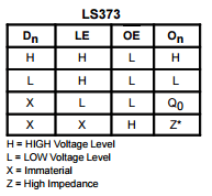
- 74LS373 is eight d-latches.When output and latch is enabled, the logic level on the input side is latched to output side.

- Output enable (OE) (active low) is tied to ground, this will keep the output side of the latches active and will never go into a high impedance state. The LED’s wont change until they’re told to change.
- Latch enable (LE) is active high, and the latch enables for the two 74LS373’s are controlled by two more IO pins on the micro controller. The micro controller can activate one latch and set one set of eight LED’s, then switch to activate the next latch and set the next set of eight LED’s with a different pattern, in effect, controlling 16 independent LED’s with eight digital IO ports.
Ir Emitter and photo transistor
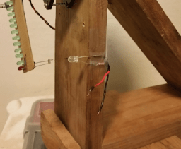
 Ir emitter pictured, attached to frame. Ir emitter is powered by the fan dc power source, with a current limiting resistor that will be suitable depending on the voltage of the fans supply. Emitter and receiver need to have a meeting point, a point where the Ir emitter will be detected by the photo transistor.
Balancing
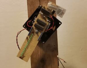
 Some balancing was needed. A piece of proto board with some washers taped to it worked. There was still some wobble to it, but much less than without a counter balance.
Software
The software consists of a few components, interrupts for handling the start position and timer, in-line delay for creating the delay between degrees of rotation, and functions for displaying text/numbers on the spinning display.
Calculations
Getting 1ms from timer interrupt
System clock is 20 MHz, one instruction takes 4 clock cycles, instruction clock is:
\[20MHz/4 = 200ns\]
With prescaler off, one interrupt with this 8-bit timer will take:
\[256*200ns = 51.2us\]
50us would be easier to work with so:
\[50us/200ns = 250\]
Timer reload value should be:
\[256-250 = 6\]
Then to get a 1ms counter, count up to 20 timer 0 interrupts.
void interrupt isr(){
 if(T0IF&&T0IE){
            t0_tpms++;
            if(t0_tpms >= 20){
                ms_counter++;
                t0_tpms = 0;
            }
       TMR0 += 6;
       T0IF = 0;
        }
}
RPM calculation
Knowing there’s 60,000 milliseconds in a minute we can get the expected number of rotations in a minute. And thus the spinning device can determine its own RPM. For my system, I’m expecting the voltage or RPM to vary, and so I have the microprocessor determine how long the delay should be between setting LED’s.
rpm = 60000/time of one rotation in ms
Delay per degree
We need to know how long one rotation takes, if we know the RPM then:
Time of one rotation in ms = 60000/RPM
Or if using a millisecond counter we can know how long one rotation takes, then its just a matter of determining how long one degree is. In terms of micro seconds:
Time of one degree = (1000us/ms) * (time of one rotation in ms) / (360 degree)
if RPM is 2700:
\[ 1000*(60000/2700) / 360 = 61.7 us \]
Knowing how long one degree is, we can decide how long of a delay to create between setting LED’s. One instruction is 200ns, and an in-line delay loop will take several instructions. one loop of a delay will take:
\[7*200ns = 1.4us\]
So to create a 61us delay:
\[61/1.4 = 43\]
void delay(){
    uint8_t adj_delay = 43;
    while(adj_delay--);
}
I combine the terms as much as I can, avoiding decimals, and using the “u” suffix on literals to let the compiler know to treat them as unsigned int, this also reduces code size as working with negative numbers takes more instructions. The calculation for delay per degree can be written as:
//(1000us*ms_counter/360 degree)(1/us per instruction clock)
//1000/360 -> 2.77 * 100/100 -> 277/100
//time of one instruction is 1/(20/4) = 200ns
//one cycle of a delay loop will take several instructions 7*200ns = 1.4us
//and there's additional instructions with setting LEDs so I pad
//the delay to 2us
delay_per_degree = (277u*ms_counter)/200u;
Interrupts
Two interrupts are used, timer 0 and external interrupt pin.
Timer
The timer is used to count milliseconds which in turn can give seconds, minutes hours, and also used in determine RPM and delay between displaying to LED’s
Interrupt on edge
The int pin is used for finding the start point in rotation. When the Ir Emitter and photo transistor cross paths, the photo transistor will react to the Ir and pull the signal line low, causing the interrupt on edge to trigger. Display The two 373 Latches make it possible to control 16 LED’s with an 8 pins. The display function takes value for writing to port pins, then sends a signal to one or both latches to to tell them to accept the value.
//Low enabled LEDs
// 0 -> outer 8 LEDs
// 1 -> inner 8 LEDs
// 2+ -> set both LEDs with same value
void set_leds(uint8_t leds,uint8_t section){
    PORTA = (leds) & 0x0F;
    PORTB = (leds) & 0xF0;

    if(section== 0){
        RB1 = 1;
        RB1 = 0;
    }
    else if(section== 1){
        RB2 = 1;
        RB2 = 0;
    }
    else{
        PORTB |= 0x06;
        PORTB &= 0xF0;
    }
}