Intro
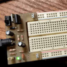
 A power supply is something every electronics project needs. To save time on prototyping a ready to go power supply is ideal. I wanted a supply that fits the breadboard nicely and can supply 3.3v or 5v. In this project a few things went wrong.
- (Problems and solutions to problems) I didn’t get a good transfer, which left some breaks in the copper traces
- fixed by soldering wire across the break
- and I didn’t use a drill press which led to a drill bit breaking
- rather than waiting to replace it I just used a larger bit which nearly destroyed the solder pads for the power jack.
- (Notes for next time) To get a good transfer, the copper surface should be clean, use acetone and steal wool, and wear gloves to avoid leaving any oils transferred from finger contact. After transferring the layout to copper surface, thoroughly check it and touch up any areas with sharpie. After etching, check the traces for continuity, if there’s any breaks, fix by soldering a jumper wire between the break.
Components
Hardware
- power jack
- switch
- LM317T regulator
- 1n4004 diode
- 2x 33 ohm resistors
- 2x 330 ohm resistors
- 220 ohm resistor
- 270 ohm resistor
- 100nF ceramic capacitor
- 10uF polar cap
- 100uF polar cap
- green LED
- Single Sided PCB
Software
- Eagle
Schematic

Design
Hardware
I wanted to have a on/off switch, selectable 5V and 3.3V and wanted the PCB such that it wouldn’t cover any of the breadboard area. I also wanted a probe point for checking current consumption (AOUT). LM317t regulator is adjustable between a wide voltage range.
The datasheet recommends 240 ohm for R1 however different resistances can work too. R1 should be chosen such that it can handle the minimum load requirement between 3.5 mA and 10 mA to maintain regulation if there is a no load situation. In the case of this project there is always a load, the resistor and LED that meet the minimum load requirement. Secondly R1 should be chosen so that in conjunction with R2 (in my schematic R2 + R3 for 3.3v and R2+R3+R4+R5 for 5v) the expected Vout can be achieved.
Vout is given by:
\(Vout = 1.25 (1 + R2 / R1)\)
\(1.25(1+ 363/220) = 3.3125V\) (When JP1 is connected)
\(1.25(1+666/220) = 5.034V\) (when JP1 is open)
I didn’t have resistors on hand with nice values for the R2/R1 ratio so a couple extra 33 ohm resistors came into play there.